
 English
 Español
 Français
 Português
400G transceiver trend

Introduction
Today, 100G is one of the most widely used technologies on the telecom/datacom market. But 5G application as well as the upgrade of services like 4K VR, Internet of Things (IoT), and cloud computing significantly increases the demand for bandwidth. Indeed, we can see a 26% annual growth rate of network traffic. Here comes 400G, considered the next-generation mainstream port technology. The 400G technology provides the ability to significantly improve the network bandwidth by using the installed set-up of interconnection helping operators and customers to cope with the massive growth of data traffic.
Today, IEEE, ITU, OIF and MSA have already released standards for 400G and are working on 800G standards to cover the future growth of data traffic.
Skylane Optics and 400G?
Skylane Optics investigated on the coming trends for 400G transceivers technology and as for 100G application, the 400G transceivers have been developed following 2 main points being high density and low power consumption. 3 main formats are coming on the market, the CFP8, a bit smaller than CFP2, the OSFP having its own thermal management and the QSFP-DD being backward compatible with the current QSFP28.
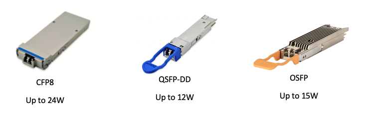
Skylane Optics is then coming with a full range of transceivers for 400G applications in order to cover all the applications and demands of the telecom/datacom market.
The schematic below shows the different standards based on distances:
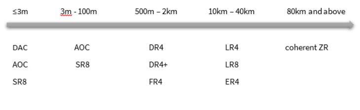
Standard naming based on distance
More options are coming to cover all the datacenter needs and Skylane Optics remains attentive to every new technology.
400G Technology
Single Mode transceivers
Transceivers using 8x 50G PAM4 like FR8: The “8” indicates the use of 8 wavelengths with each one operating at 50G PAM4. The 8 wavelengths are multiplexed into one fiber through a duplex LC interface.
Some transceivers, such as the 2x FR4, also use 8 lasers but are divided into 2 groups with four wavelengths. These 2 groups are multiplexed each into a fiber and the transceiver offers a 2x200G interface on dual CS connectors.
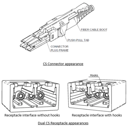
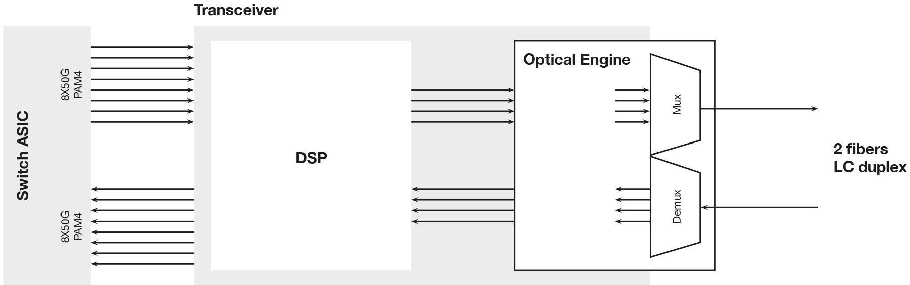
Transceivers using 4x100G PAM4: Those are the current market focus and use 4 lanes with 100G PAM4. Here we can group the transceivers into “Multi Fiber” and “Two fiber” types. The key element in these transceivers is the DSP with its gearbox function.
For instance, in the DR4 transceivers the DSP converts the 8x50G PAM4 electrical host signals into 4x 100G electrical lanes towards the optical engine. At the same time the DSP acts as a CDR. In a DR4 the optical engine (EML lasers or Silicon Photonics SIP based) generates and terminates the optical lanes. Each lane operates at 1310nm and requires one fiber. In other words, the transceiver interface needs to have 8 fibers.
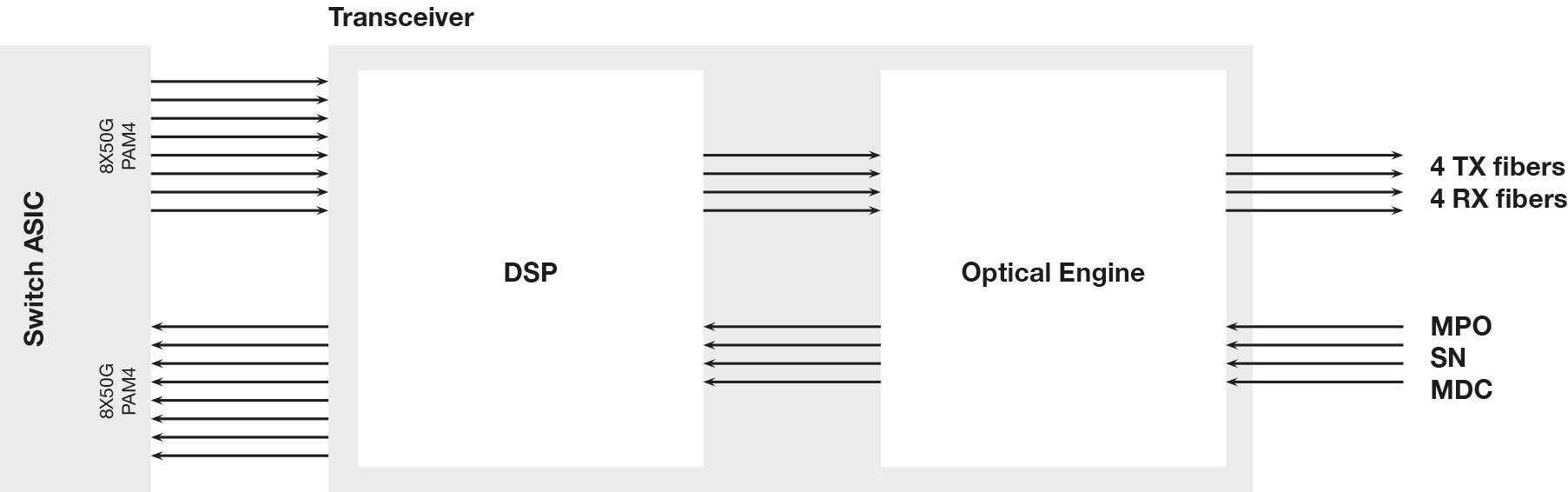
In the case of FR4 and LR4, the basic function of the DSP is the same as in the DR4, but now 4 wavelengths (CWDM4 grid) are being used instead of 4x 1310 signals and a multiplexer is added to combine these CWDM signals together. By this, the number of required fibers is reduced to 2 (TX + RX). The transceivers have duplex LC interfaces.
Multimode Short Reach (SR) transceivers
The main trend goes to SR8 (IEEE802.3cm) and SR4.2 (MSA BD4.2).
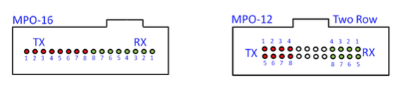
In case of the SR8, the “8” implies there are 8 optical channels on 8 separate fibers. A total of 16 fibers (8 Tx and 8 Rx) are needed as each optical channel operates at 50G PAM4. The SR8 module uses either an MPO-16 connector or a 2 row MPO-12 connector to connect to 8 fiber pairs. The most common implementations use 2 row MPO-12.
When talking about the SR4.2, the “4” implies there are 4 optical channels using 4 separate fibers and the “2” means that each channel uses 2 different wavelengths. A total of 8 fibers are needed as each optical channel operates at 2x50G PAM4. The wavelengths are bi-directional and multiplexed. The SR4.2 module uses an MPO-12 connector.
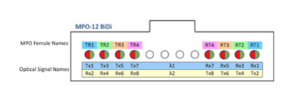
The big interest of the SR4.2 is to be able to re-use the existing cables placed in the current installations.
400G Optics Summary
| Description | Electrical interface | Operating wavelength () | Optical lane | Connector | Distance |
|---|---|---|---|---|---|
| SR8 | 8x50G | 850 | 8x50G | MPO-16 | 100m |
| SR4.2 | 8x50G | 850/910 | 8x50G Bidi | MPO-12 | 100m |
| DR4 | 8x50G | 1310 | 4x100G | MPO-12 | 500m |
| DR4+ | 8x50G | 1310 | 4x100G | MPO-12 | 2km |
| 2x FR4 | 8x50G | 2x (1271/1291/1311/1331) | 8x50G | CS | 2km |
| FR4 | 8x50G | 1271/1291/1311/1331 | 4x100G | LC | 2km |
| FR8 | 8x50G | 1275/1277.5/1282.5/1285/1295/1300/1305/1310 | 8x50G | LC | 2km |
| LR4 | 8x50G | 1271/1291/1311/1331 | 4x100G | LC | 10km |
| LR8 | 8x50G | 1275/1277.5/1282.5/1285/1295/1300/1305/1310 | 8x50G | LC | 10km |
| ER4 | 8x50G | 1295/1300/1305/1310 | 4x100G | LC | 40km |
| ER8 | 8x50G | 1275/1277.5/1282.5/1285/1295/1300/1305/1310 | 8x50G | LC | 40km |
Sources:
- 400G and 100G PAM4 Transceiver Interfaces
- Arista 400G Architectures and Optics Overview
 Data Sovereignty Begins at the Hardware
 High-Performance Optics for the Memory Crunch
 Celebrating 4 Years as Part of the Amphenol Family
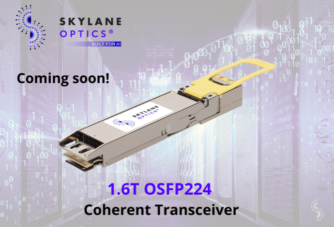 A New Era: 1.6T OSFP224 2xDR4 Transceivers
 Expand Your Optical Network with EDFAMUX